Following on from his previous posts: Bending the Law of Sines, which introduced the idea of tricurves, and a further post on Combining Tricurves, Tim Lexen continues this series of guest posts by looking at some of the structures underlying tricurve tilings.
When we look at simple planar shapes for tiling, usually each shape’s properties and tiling structure are obvious. The framework for the tiling is usually defined by the shape in a straightforward manner. But here we’ll look at the uniquely useful arrangement of the tricurve’s arc centers—which is not obvious—and use this structure to add a dimension to the tiling.
A tricurve has its three arcs, and these arcs have centers as shown below.
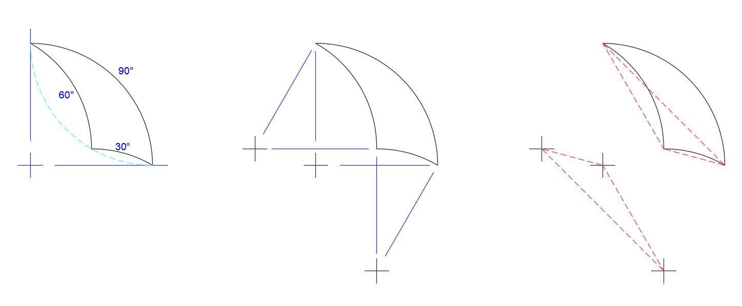
The three arc centers make a familiar pattern: they form vertices of a triangle matching that of the tricurve corners, rotated 180°. So there is underlying structure to the tiling: when two tricurves are adjoining, they share an arc and thus share arc centers. The new triangle by itself it not so interesting, but then we realize we can place another identical tricurve over that triangle, matching at the corners. This is rotated 180°, about a point between the shapes:

Let’s call the second, identical shape the “phantom” of the original tricurve. It will be shown here in phantom line style. Note this phantom is also constructed of arcs using the original tricurve vertices as the arc centers. So you have a self-referencing pair of shapes (having rotary inversion symmetry). The phantom is paired and linked to its (original) tricurve, like the Yin-Yang symbol.
What happens when we tile with the single tricurve and its phantom? To start out we can tile periodically, and phantoms follow suit:
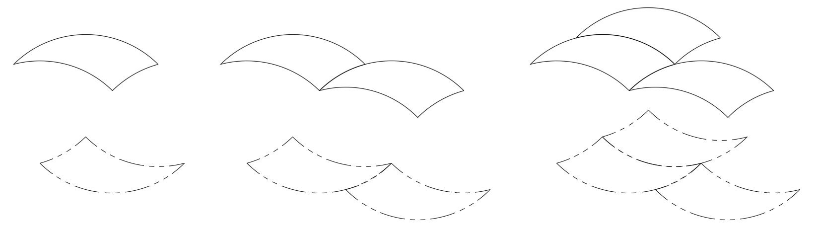
This is not too surprising, since this could be done with a 180° phantom paired at any location and distance. This also works when we make periodic tiling in alternating directions with mirror images of the pair:
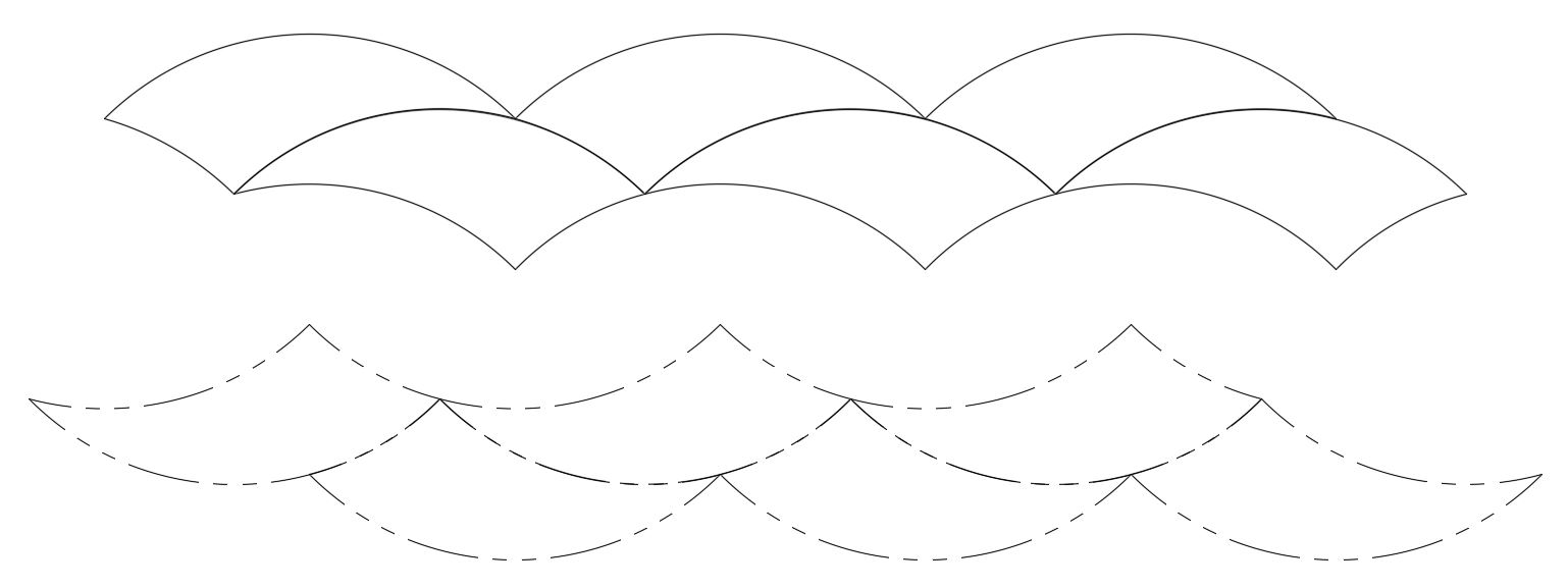
But the real surprise comes when we do the more complex, non-periodic tiling:

Here the phantoms also tile, making a workable, inverse tiling group. But the phantom tiling group isn’t merely a 180° rotation of the original tiling group. If the phantom group is separated and rotated 180°, the arrangement is still different, as shown below. Each phantom is now back in the same orientation as its original; but relative to a reference point—such as the red tricurve—each phantom is transposed to the opposite side.
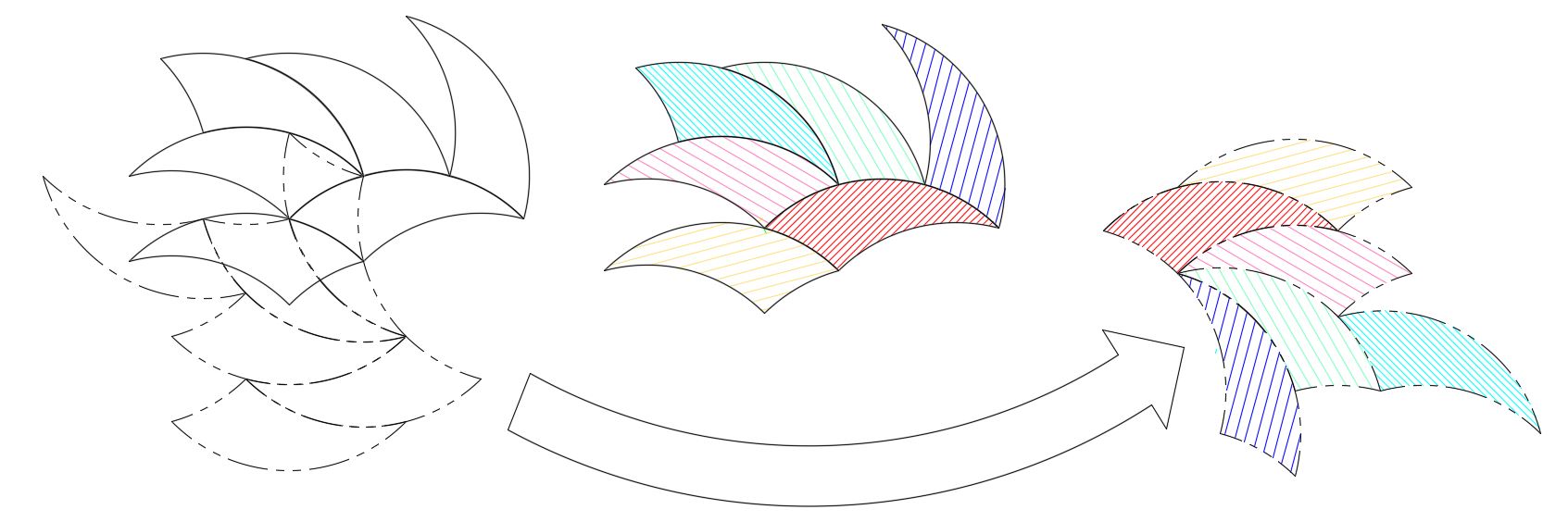
This is also shown below when we use a starting radial pattern (star) with the tricurves (red shading). Whichever small corner angle we use at the center, the phantoms (blue shading) surround a circular hole. As the pattern is extended outward, the phantoms also build outward from the hole.

Tiling with phantoms feels odd, as you are doing two things at once. You slide each original tricurve into its place, while watching the phantom pop into its own place automatically. Although the two parts move together, they each fit into place differently. This tiling is best done a computer, preferably on graphics software that lets you put the phantoms on a separate layer that can be turned on and off.
The above examples all use the 30°-60°-90° tricurve for simplicity; it’s easy to visualize. But this works for all tricurves: that is, as for tricurve tiling in general, the periodic phantom tiling works for any tricurve, and the polar and non-periodic phantom tiling works for any tricurve with agreeable angles and arcs (multiples of 12° or 15°).
Each shape of tricurve has a unique relationship to its phantom:
We can see three categories of relationships between a tricurve and its phantom: 1) no overlap; 2) point contact; and 3) overlap. It is easiest to start with the cases of point contact, since they separate the two other cases.
There is single point contact for the single case of the 60-60-120 tricurve:

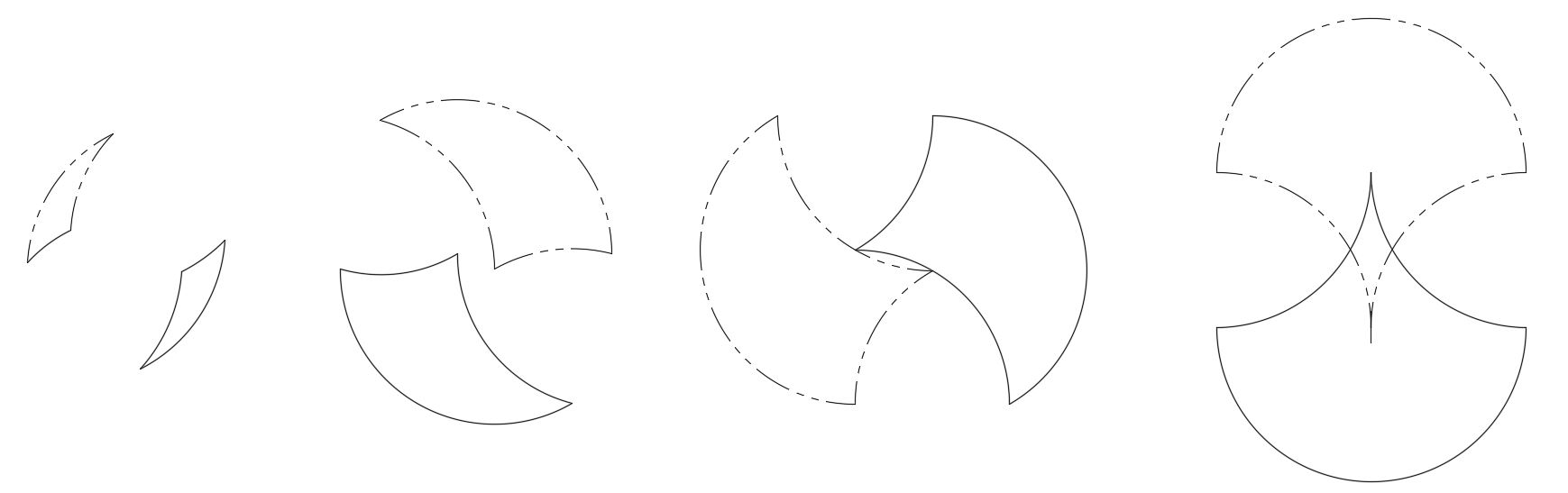
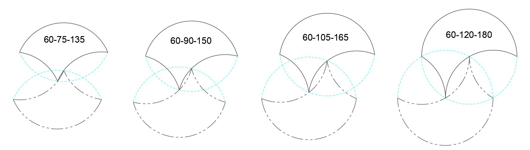
There is two-point contact when the largest arc is greater than 120° (of course up to 180°) and the smallest minor arc is exactly 60°. This is shown below for four large arcs.
There is no overlap between tricurve and it phantom when the largest (convex) arc is less than 120°, regardless of the two smaller arcs. And there is no overlap when the largest angle is greater than 120° and the smallest minor (concave) arc is less than 60°. This case is the easiest to visualize, and includes examples shown earlier.
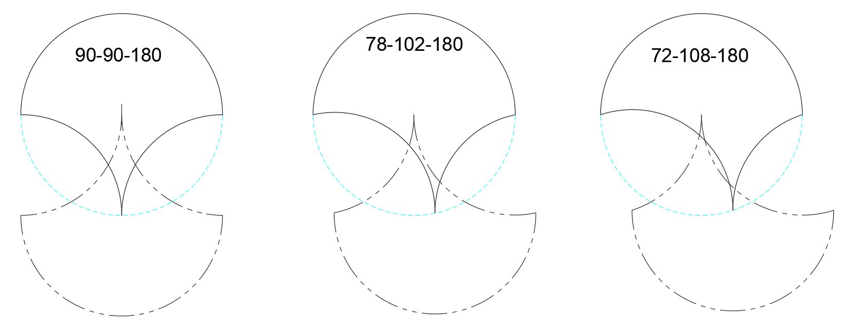
There is overlap between tricurve and its phantom when the largest arc is greater than 120° and the smallest minor arc is greater than 60°. The figure below shows examples of overlap when the large arc is 180°, with the one on the left showing maximum overlap of any tricurve.
Do you notice something that all the tricurve-phantom pairs have in common?
The two open areas between the tricurve and its phantom always have the same shape. This is shown below by fitting a red equilateral triangle in place. Where there is point contact or overlap, we can draw two equilateral triangles between the outermost tricurve corners and the intersection point. Where there is no overlap we can do this by extending one or both concave curves (in blue dashed lines). Below, only one of the equilateral triangles is shown in each case, for clarity. The real or extended concave arcs on each side are 60°, bounding the equilateral triangle (as convex arcs), and forming two sides of what would be a Reuleaux triangle. The equilateral triangles all have side lengths of one unit, which is also the arc radius.
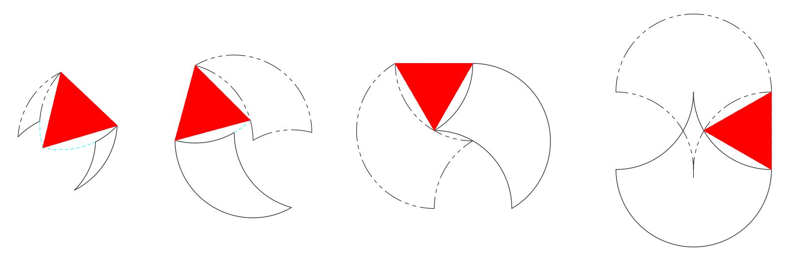
This fitting of the equilateral triangle within the two 60° arcs makes sense, when you remember that 1) the outermost corners are one radius apart, and 2) the two 60° arcs center on those corners.
So we have seen that the tricurve’s arc centers reflect the basic structure, and can be used as a basis for a rotary-inverted twin shape. This leads to surprising relationships between each pair of shapes, and to some interesting situations with the dual tiling. This shows what is going on behind the scenes in tricurve tiling. Please try this out: play, explore, and share what you find!